-
Craft Info Galleries
- Full Galleries Listing
- Special Galleries
- BAe/Aerospatiale CONCORDE >>>
- Concorde
- A Brief History
- Aircraft Caricatures
- VIDEO: BA Engineering Tour
- Various Concorde photographs
- Concorde at The Queen's Jubilee, 2002
- Landing at Heathrow, May 2002
- 20/10/03 Birmingham Landing (G-BOAC)
- 21/10/03 Belfast Landing
- 22/10/03 Manchester Landing (G-BOAG)
- 23/10/03 Cardiff Landing
- 24/10/03 Final Day Heathrow Landings
- Tiger 4 in Antarctica
- Military Hovercraft
- Human Powered: Steam Boat Willy
- Model Hovercraft
- Paper Hovercraft
- Hovercraft Museum Collection >>>
- Hovershows
- Hovershow 2004
- Hovershow 2009
- Hovercraft Museum Open Day 2011
- Bell hovercraft
- Cushioncraft
- Denny Hovercraft
- Griffon Hovercraft
- Hoverdevelopment Hovercraft
- Hoverhawk
- Military hovercraft
- Russian hovercraft
- SEDAM Hovercraft
- Vickers hovercraft
- Vosper-Thornycroft
- Other hovercraft makes and models
- Theory and hoverports
- British Hovercraft Corporation
- Concept craft by BHC
- The AP1-88 in development
- The AP1-88 in service
- The BH7
- The SRN1
- The SRN2
- The SRN3
- The SRN4 in development
- The SRN4 in service
- The SRN5
- The SRN6
- Hovercraft Chronology
- NRDC SRN1
- Vickers VA.3 >>>
- Westland/BHC SRN2 >>>
- Westland/BHC SRN3
- BHC SRN4 (Mountbatten) >>>
- Main SRN4 Information Page
- 1982 Hoverspeed Brochure
- BHC SRN4 Info booklet
- BHC Promotional Leaflet
- SRN4 featured in "Tell Me Why" magazine, 1968
- SRN4s operating with Hoverlloyd
- SRN4s operating with Seaspeed
- SRN4s operating with Hoverspeed
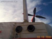
- SRN4 Features Tour
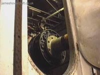
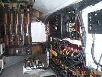
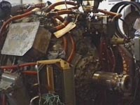
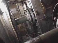
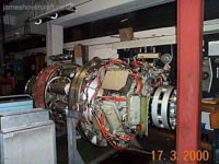
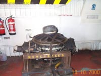
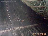
- SRN4 Systems Tour
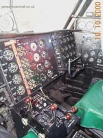
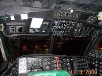
- SRN4 Cockpit Tour
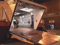
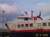
- 1974 Skirt damage to The Princess Anne (a recollection)
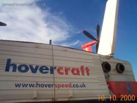
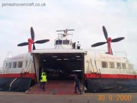
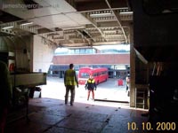
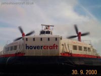
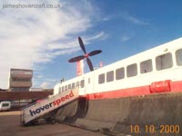
- Last days of SRN4 Service (Sept-Oct 2000)
- SRN4s at Hovercraft Musuem Open Day 2011
- BHC SRN5 (Warden)
- BHC SRN6 (Winchester) >>>
- Main SRN6 Information Page
- SRN6s at Ramsgate, 1960's, with Hoverlloyd
- SRN6s with Hoverlloyd (J Lawrence)
- SRN6s with the Canadian Coastguard (P Brett)
- SRN6s at Cowes, with Seaspeed (J Lawrence)
- SRN6s at Southsea, Ryde, with Hovertravel (J Lawrence)
- SRN6s operating with the Inter-Service Hovercraft Trials Unit (J Lawrence)
- SRN6 Twin-Prop at the Hovershow 2009
- BHC BH7 (Wellington)
- Hovermarine HM2
- Vosper Thornycroft VT-2
- SEDAM N500 (Naviplane)
- BHC/Hoverwork AP1-88
- Air Vehicles Tiger 12
- Hoverwork BHT-130
- Pat's Galleries >>>
- SRN2 Hovertransport Ltd. Eastney to Ryde service (1964)
- SRN3 with the Inter-Service Hovercraft Trials Unit (IHTU)
- SRN4 with Hoverspeed (Early days, Later days); Seaspeed; and at BHC's Falcon Yard works
- SRN5 with the IHTU
- SRN6 with Seaspeed at Cowes; with Hovertravel at Southsea; with Hoverlloyd at Ramsgate; with the IHTU
- Search-and-Rescue Osprey 5
- BAA's Hoverguard 80
- Griffon 2000
- LDLines Incat 112
-
Videos
-
World Hoverports
-
Hovercraft Shop
-
Other Sites of Interest
-
How It Works
- Introduction to terminology
- Concepts and Theory of Hovercraft
- Human-Powered hovercraft as a working demonstration
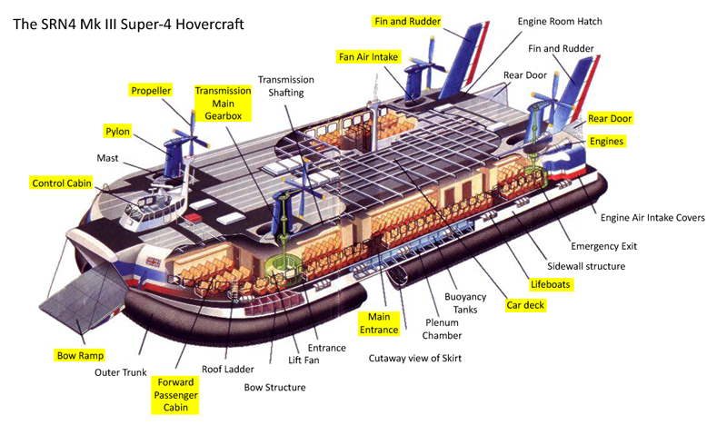
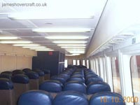
- Features of typical hovercraft (SRN4)
- Cockpit of hovercraft (SRN4)
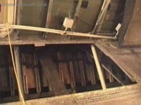
- Hovercraft Control Systems (SRN4)
- The earliest hovercraft (SRN1)
- The first passenger hovercraft (VA-3)
- Hoverports (Dover)


-42.jpg)
-21.jpg)
-37.jpg)

-07.jpg)


-38.jpg)


-40.jpg)