Previous: SRN4 Cockpit 
 Next: SRN1
This page is intended as a brief diagramatic overview of three important control systems on the SRN4. The basics of these systems can be applied to all types of hovercraft, with subtle differences in some case such as the orientation of the lift fan, or bigger changes in the case of separate drive and lift engines, or even single fan setups with bleed air from thrust going to feed lift (such as in single engine racing hovercraft). The systems on this page fit in with those talked about previously in the Cockpit Tour and the Features Tour, so be sure to check those out before reading this page if you want a better understanding of the concepts demonstrated here.
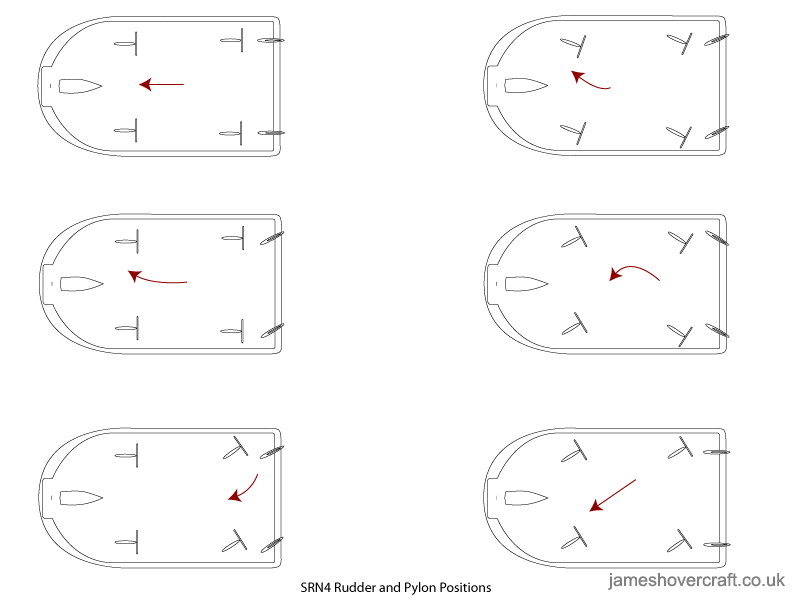
Steering system
A sample of the various configurations of pylons and fins on the SRN4. The red arrows show the resultant direction of motion of the craft under each condition. Assume all thrust is normal for forward motion (positive pitch).
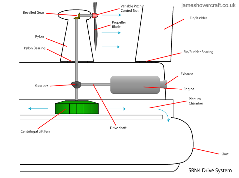
Thrust system
Here can be seen a side cutaway view of the components of the thrust system. Note the splitter gearbox attached to the engine driveshaft, leading to the centrifugal lift fan and the main drive propeller.
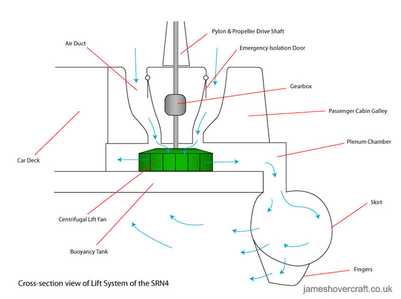
Lift system
This diagram shows the components of the lift system from a transverse cutaway view. Note the two air ducts leading to the lift fan, and the motion of air as it enters the skirt from the plenum chamber. The two emergency doors shown are those described in the Features Tour, automatically slamming shut in the event of engine failure causing escaping lift air.
And that's it for the theoretical part of the tour! The next few pages are case studies of the development of the hovercraft, from its early days with the SRN1 and VA-3, to the present day's AP1-88 services. I hope you have found this informative and interesting so far, any questions or suggestions feel free to contact me!


